WebRTC

Web Real Time Communication (WebRTC) is a free and open-source project providing web browsers and mobile applications with real-time peer-to-peer communications. Its specification is still an ongoing work as a cooperative effort between the World Wide Web Consortium (W3C) defining the APIs and the Internet Engineering Task Force(IETF) standardizing the protocols.
Index
Signaling
WebRTC uses a peer-to-peer distributed architecture. Although public APIs and protocols are standardized, the initial negotiation and communication establishment is up to the application to implement. This initial handshaking should take care of simple stuff, such as letting one peer know when the other is calling, or more complex stuff like establishing a unique session between two peers and sharing offers, answers and candidates. The part of the application that is in charge of these is called the signaling server.
A signaling server should handle:
- Authentication. Exchange certificates for secure communication.
- Media capabilities. Both peers need to agree on the media formats the session will support.
- Connection endpoints. Each peer needs to know how to send data to the other peer.
It is up to the application to ensure that this out-of-band signaling is performed securely and remains accessible to both peers. While WebRTC itself does not mandate a specific signaling protocol, efforts have been made to standardize signaling for particular use cases. In the broadcast and streaming industry, this need is being addressed by two emerging protocols:
WHIP (WebRTC-HTTP Ingestion Protocol) standardizes the process of sending media from a client to a server by standardizing how SDP offers and ICE candidates are exchanged over HTTP endpoints. It is designed to work well with existing HTTP-based infrastructure and CDN workflows where live streams are ingested into servers or cloud platforms.
WHEP (WebRTC-HTTP Egress Protocol) standardizes the process of receiving media from a server to a client by standardizing how SDP offers and ICE candidates are exchanged over HTTP endpoints. It enables consistent and interoperable playback mechanisms for broadcast delivery.
Both WHIP and WHEP aim to bring interoperability and simplicity to WebRTC deployments by avoiding custom signaling implementations, especially in large-scale or production-grade environments. They are lightweight, HTTP-based protocols that fit well into traditional media and CDN pipelines, enabling efficient real-time media transport over standardized interfaces.
Connectivity
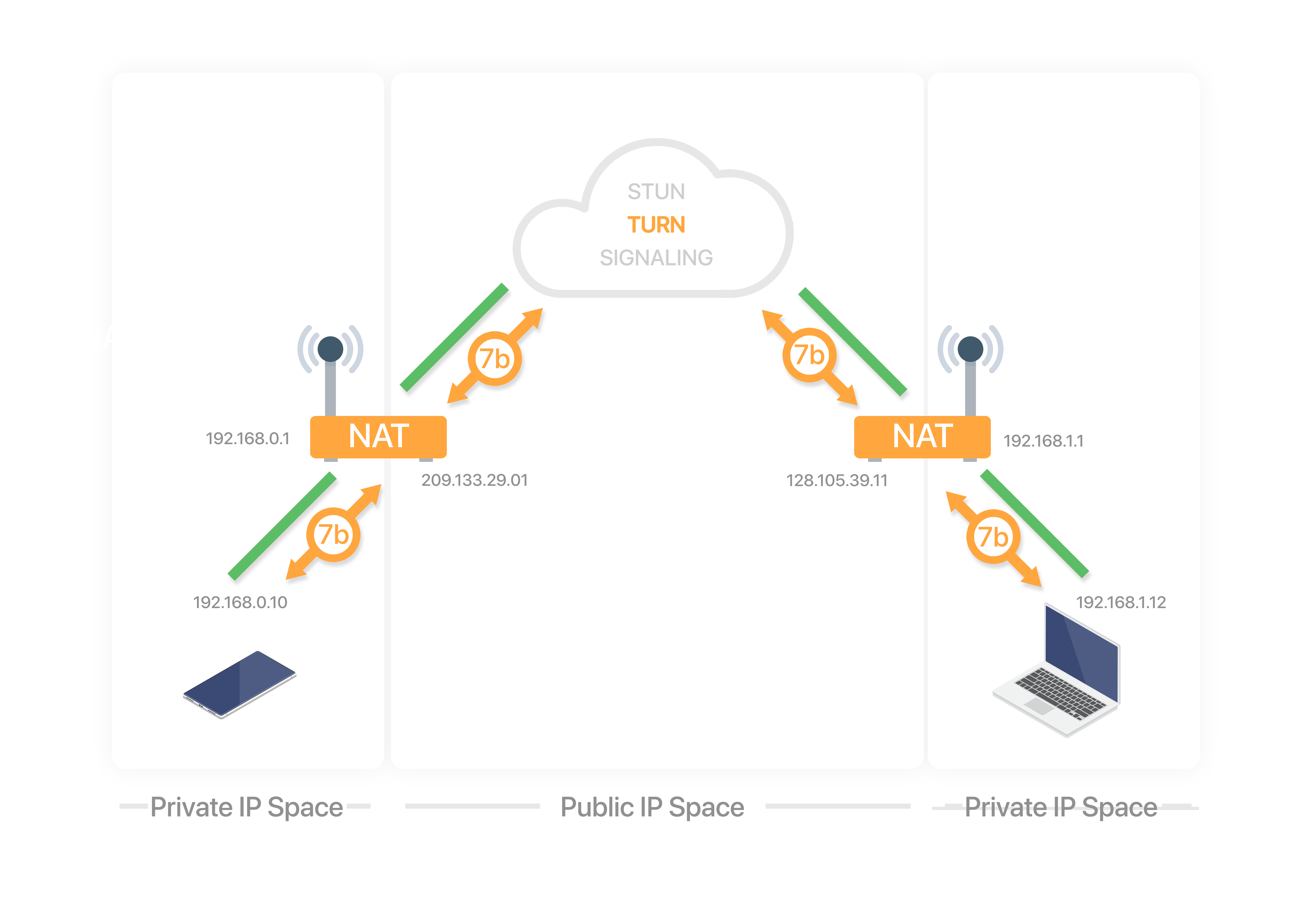
Interactive Connectivity Establishment (ICE) is a protocol for Network Address Translator (NAT) traversal used in computer networking to find ways for two computers to talk to each other as directly as possible in peer-to-peer networking.
In a real world scenario, establishing a WebRTC connection between 2 peers, caller and callee, using ICE has the following steps:
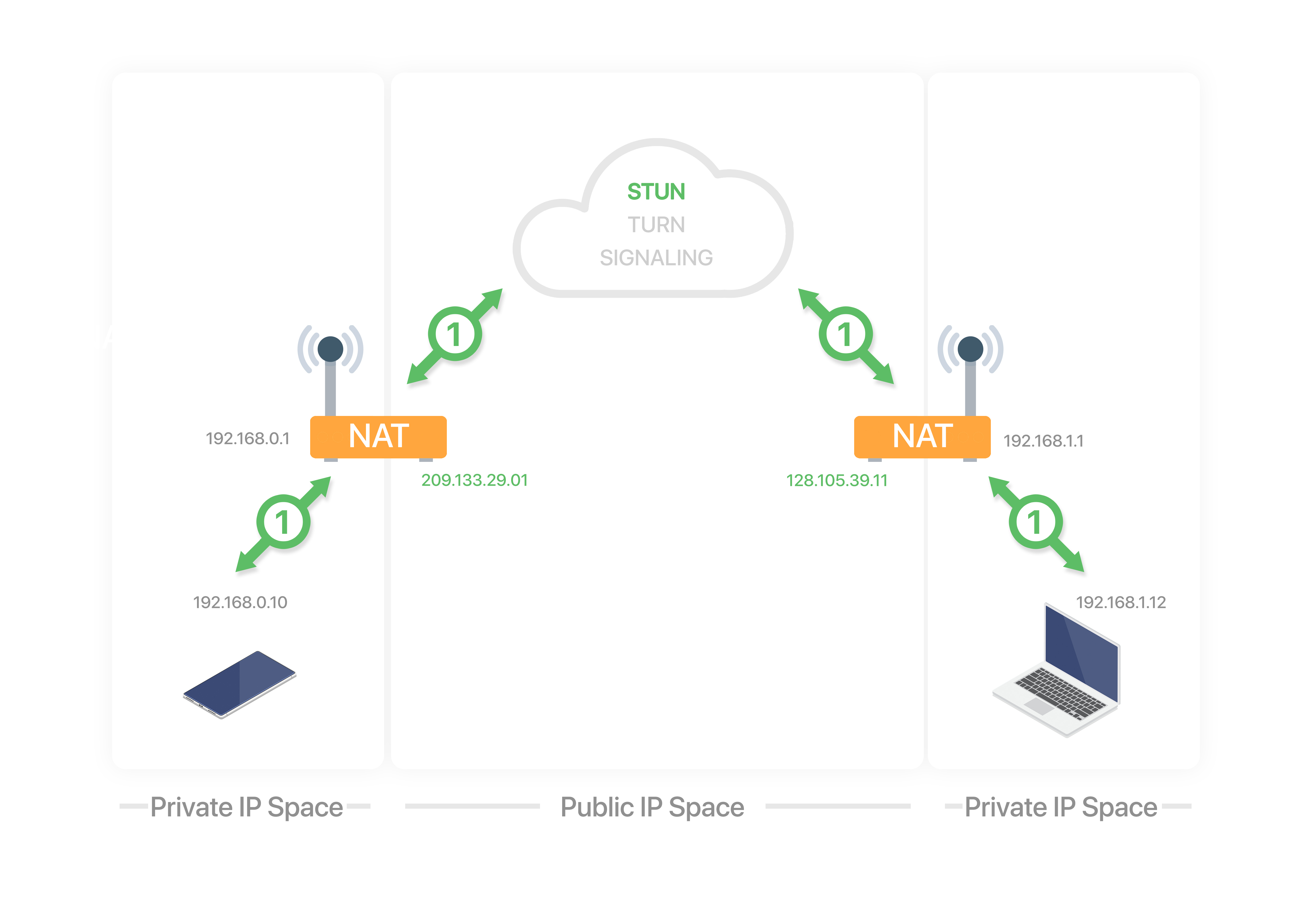
1. Address discovery
Each peer is located in a LAN behind a NAT and has a private address, to discover their public addresses each peer uses the Session Traversal Utilities for NAT (STUN) server.
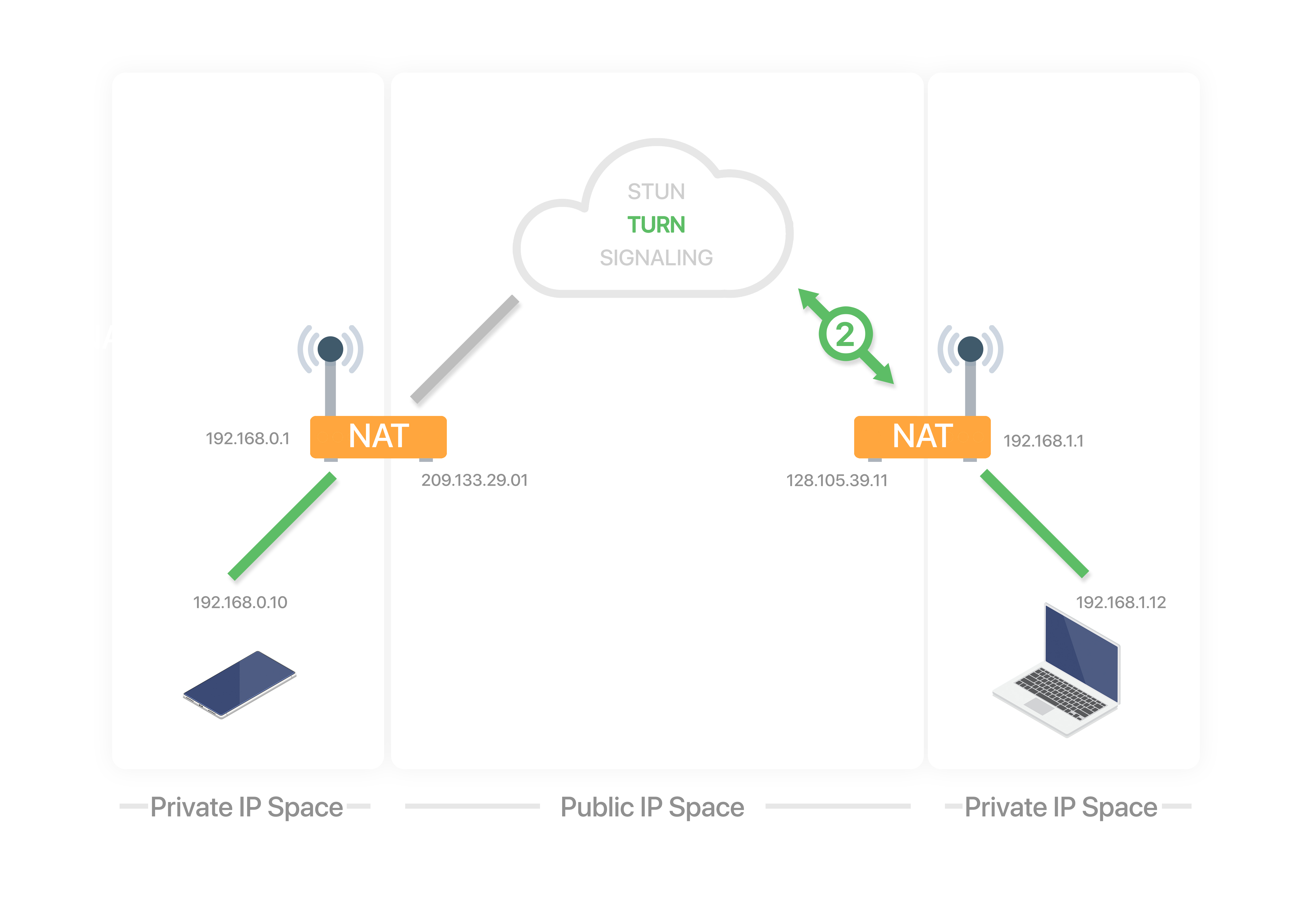
2. Caller relay allocation
The caller allocates a connection in the Traversal Using Relays around NAT (TURN) server. The TURN server relays the data between two peers when a direct connection is not possible.
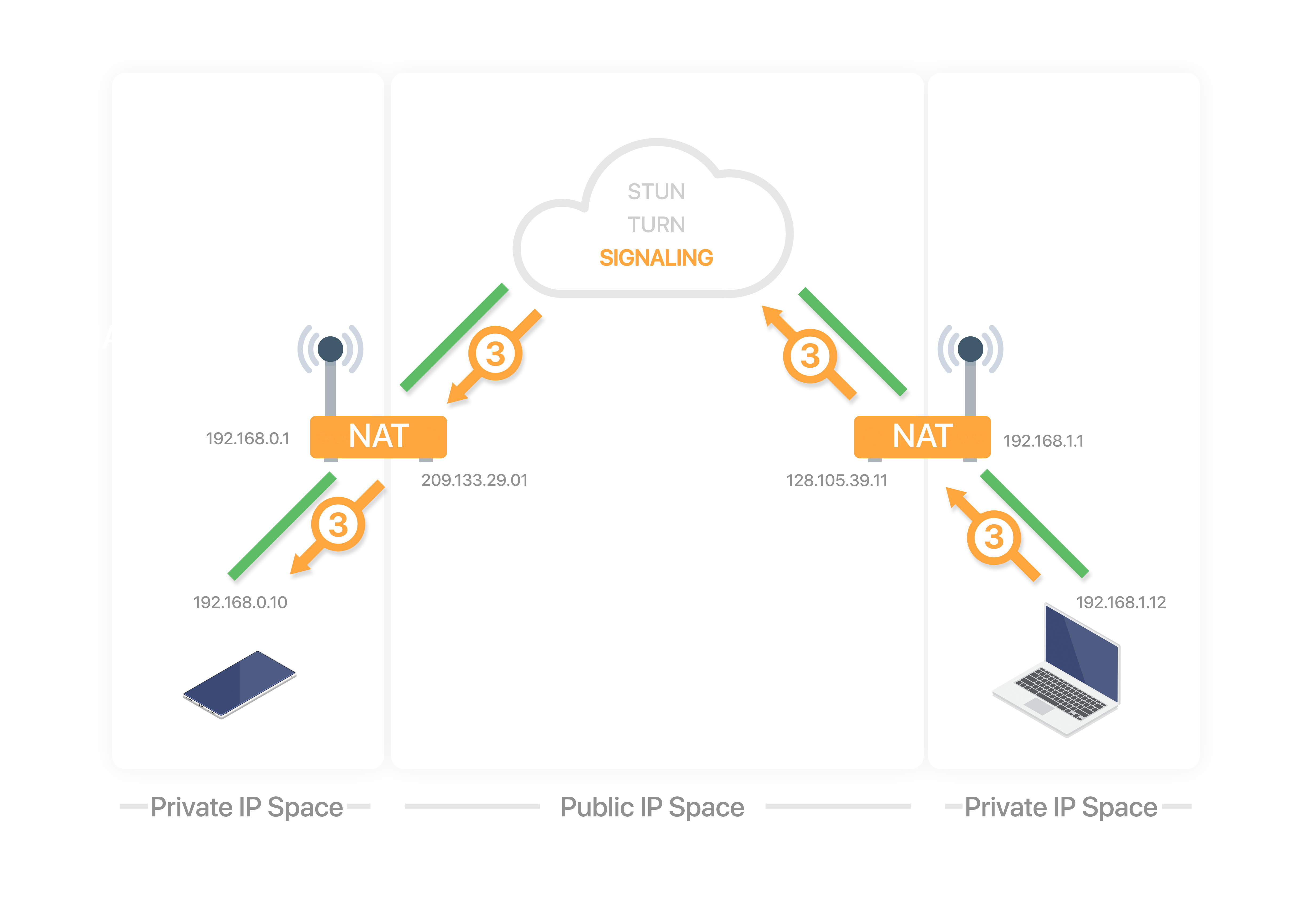
3. Caller sends offer
The caller sends a connection offer to the callee using a signaling server (both peers are already registered in the signaling server).
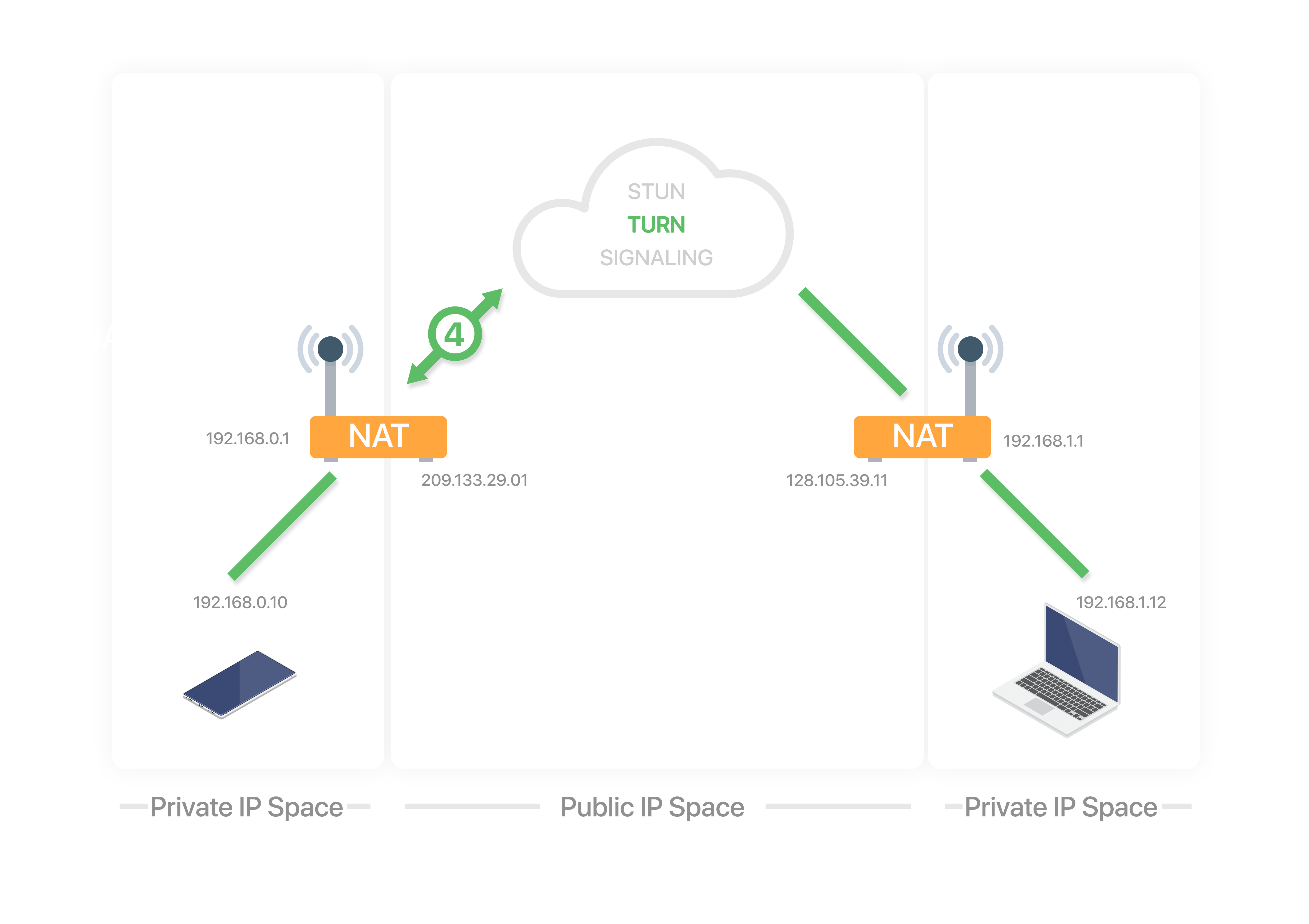
4. Callee relay allocation
The callee receives the offer and allocates a connection in the TURN server.
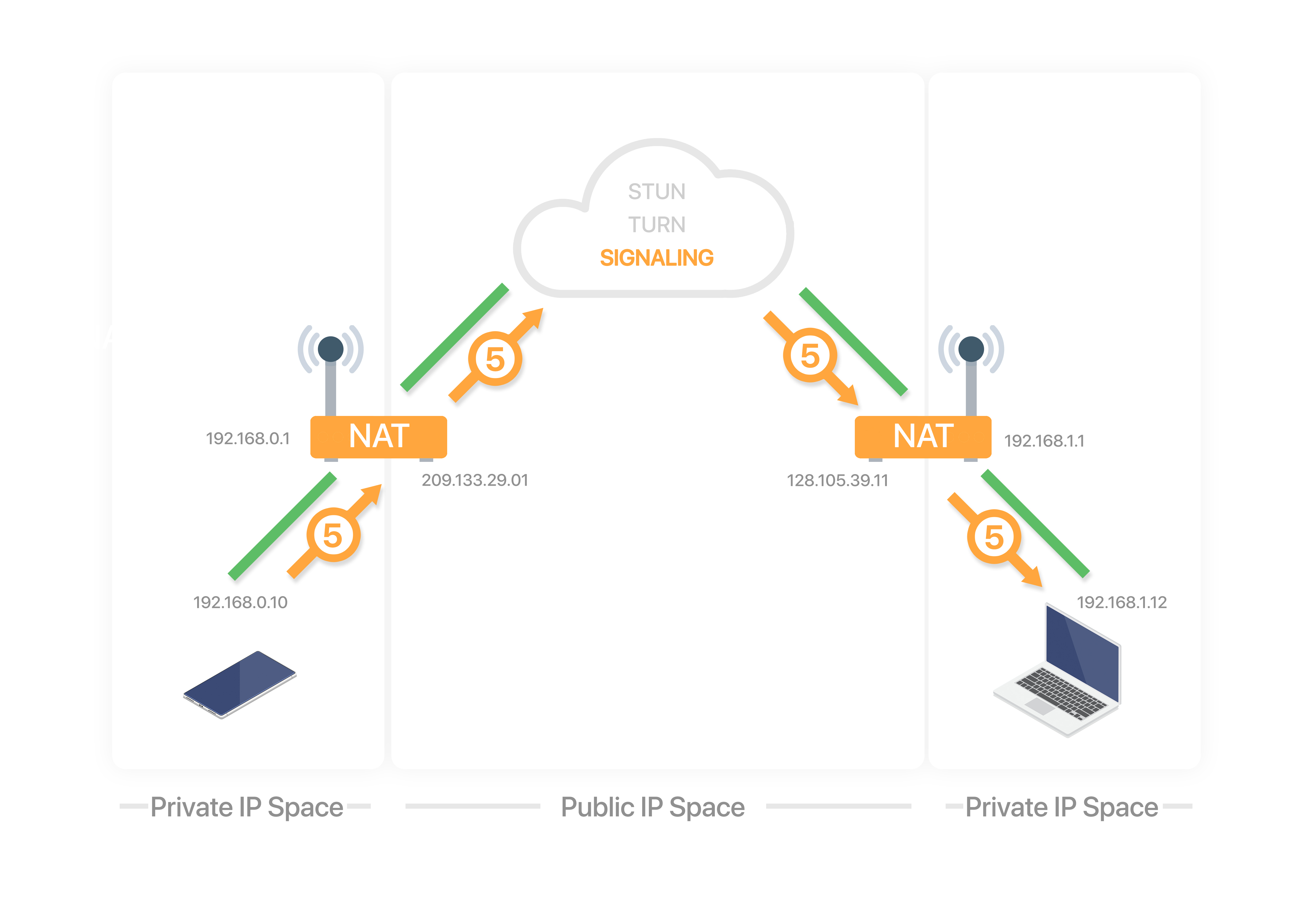
5. Callee sends answer
The callee sends a connection answer to the caller using the signaling server.
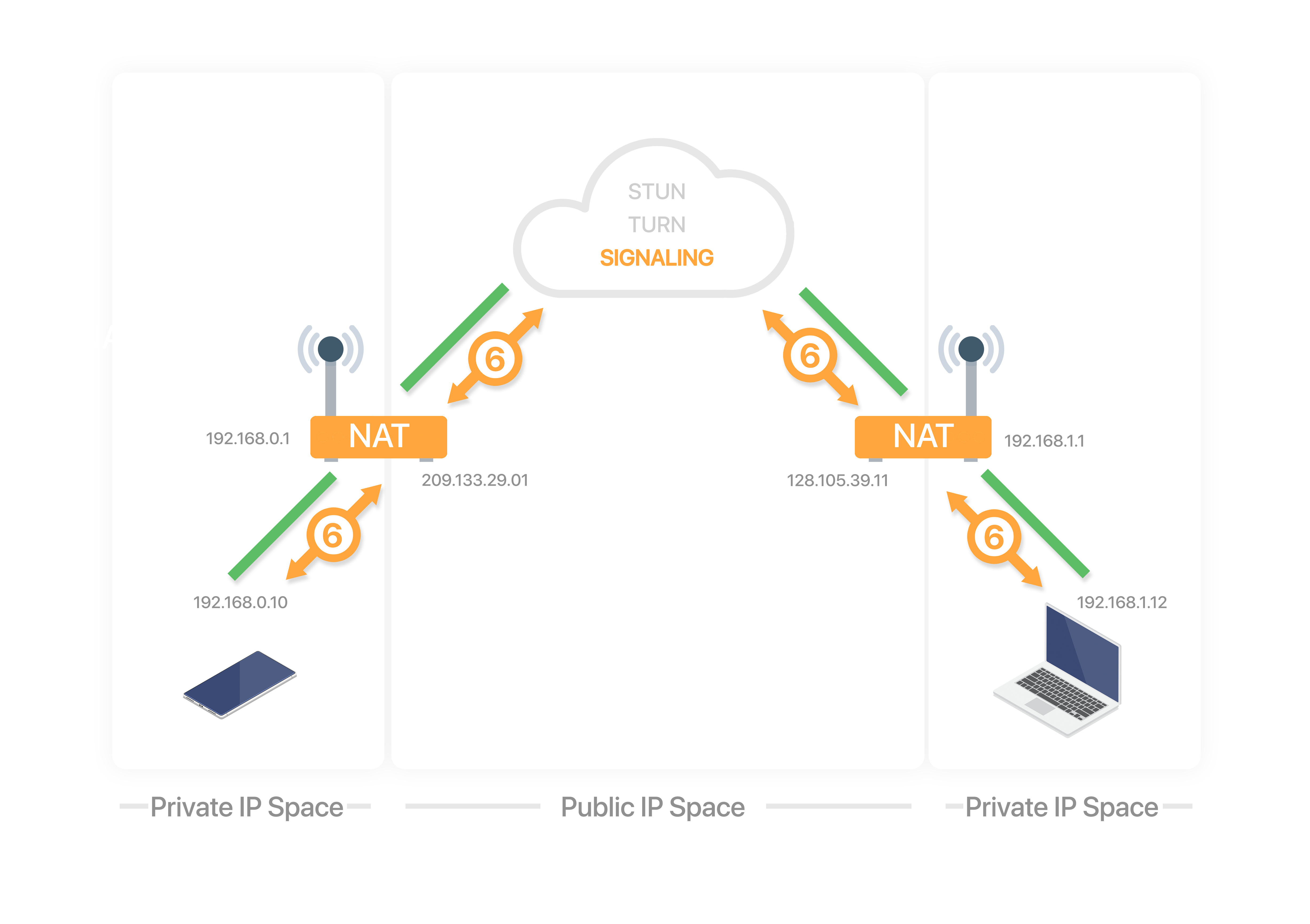
6. Candidate exchange
During the offer/answer process, each peer gathers candidates to be used for ICE. Each candidate is a potential address/port to receive the data. There are 3 types of candidates:
- Host. Generated by the peer by binding to its private IP addresses and ports.
- Reflex. Generated by sending query messages to a STUN/TURN server. The query passes through the NAT which creates a binding. The response to the query contains the public IP and port that was generated for the binding.
- Relay. Generated by sending query messages to a TURN server. The query passes through the NAT which creates a NAT binding. The response to the query contains the public IP and port that was generated for the binding.
After each candidate is gathered, the candidate is exchanged with the other peer via the offer/answer or standalone using trickle ICE.
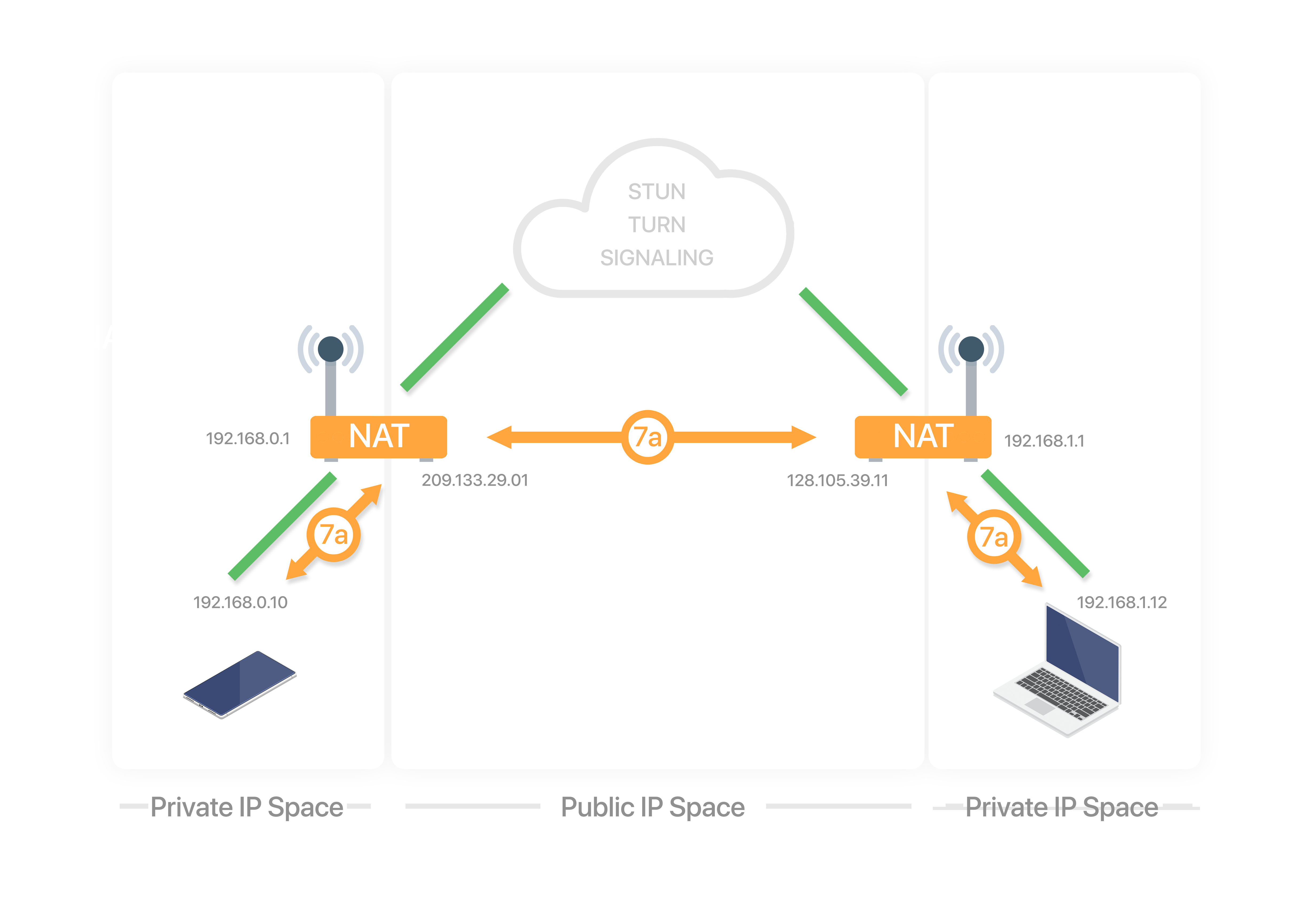
7a. Check direct connection
Each peer has an ICE agent making connectivity checks:
- Matches its local candidates with its remote candidates, creating candidate pairs.
- Sends connectivity checks every 20ms, in pair priority, over the binding requests from the local candidate to the remote candidate.
- After receiving the request, the agent generates a response.
- If the response is received, the check has succeeded.
This process may produce additional candidates known as peer reflexive candidates. This happens when there is a symmetric NAT in between peers. During the connectivity check process, a STUN request is sent directly to the peer, which can generate a brand new binding. If it does, the STUN response is sent back informing the originating peer that a new binding was formed. This allows peers to have a direct media path between them, even in the presence of a symmetric NAT.
| NAT Type | STUN support |
|---|---|
| Full Cone NAT | Yes |
| Address Restricted Cone NAT | Yes |
| Port Restricted Cone NAT | Yes |
| Symmetric NAT | No |
7b. Use relay connection
When a direct connection is not possible, the relay candidates are used. TURN servers are guaranteed to work because they are publicly available, unless NATs are specifically configured to block them.
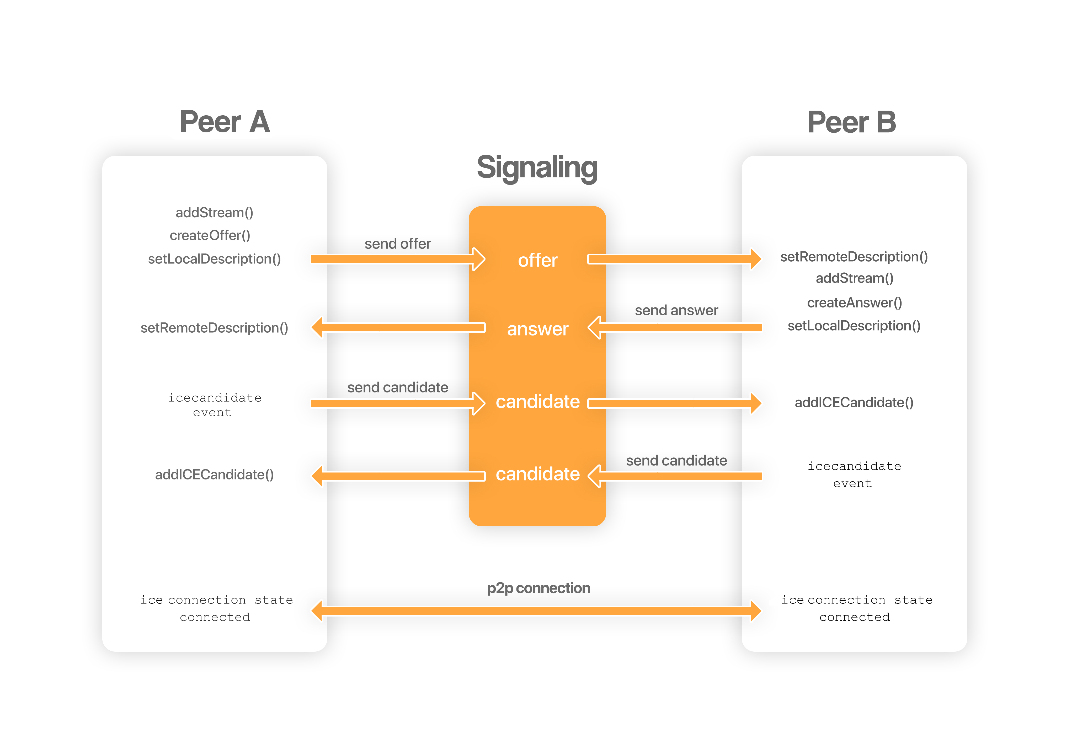
A complete message flow of a peer to peer connection establishment is shown in the diagram below:
Media
WebRTC establishes a baseline set of codecs which all compliant applications are required to support. Applications may choose to allow other codecs as well. The minimum codecs required are:
Media streams (audio and video) are delivered through Real-time Transport Protocol (RTP). This protocol was designed to ensure timely and ordered packet arrival while tolerating data loss due to unreliable channels. RTP is usually used in conjunction with Real-time Transport Control Protocol (RTCP), which provides statistics, quality-of-service and synchronization data to the participants of the session.
Some of the packets sent using RTCP are:
- Receiver Estimated Maximum Bitrate (REMB). Used to provide bandwidth estimation in order to avoid creating congestion in the network.
- Picture Loss Indication (PLI). Used to request the sender to send a new keyframe.
Session Description Protocol (SDP) is the protocol used to represent the media capabilities of each peer. SDP is already used in other protocols like Real Time Streaming Protocol (RTSP) or Session Initiation Protocol (SIP) in streaming applications such as voice over IP (VoIP).
A SDP is generated and sent from each peer during the offer/answer process. A SDP has the following structure:
Session
v=  (protocol version number, currently only 0)
o=  (originator and session identifier: username, id, version number, network address)
s=  (session name: mandatory with at least one UTF-8-encoded character)
i=* (session title or short information)
u=* (URI of description)
e=* (zero or more email address with optional name of contacts)
p=* (zero or more phone number with optional name of contacts)
c=* (connection information—not required if included in all media)
b=* (zero or more bandwidth information lines)
One or more time descriptions ("t=" and "r=" lines; see below)
z=* (time zone adjustments)
k=* (encryption key)
a=* (zero or more session attribute lines)
Zero or more Media descriptions (each one starting by an "m=" line; see below)
Time
t=  (time the session is active)
r=* (zero or more repeat times)
Media
m=  (media name and transport address)
i=* (media title or information field)
c=* (connection information — optional if included at session level)
b=* (zero or more bandwidth information lines)
k=* (encryption key)
a=* (zero or more media attribute lines — overriding the Session attribute lines)
Example 1
v=0
o=- 0 0 IN IP4 10.47.16.5
s=session9000
c=IN IP4 224.2.17.12/127
t=0 0
m=audio 8080 RTP/AVP 111
a=rtpmap:111 OPUS/48000
m=video 9090 RTP/AVP 96
a=rtpmap:96 VP8/90000
- Session named
session9000. - NTP timestamps for start and end of the session
0 0. - Audio:
- RTP port
8080. - RTCP port
8081(RTP+1). - RTP Profile for Audio and Video (RTP/AVP).
- Payload type
111corresponds to codecOPUS/48000.
- RTP port
- Video:
- RTP port
9090. - RTCP port
9091(RTP+1). - RTP Profile for Audio and Video
RTP/AVP. - Payload type
96corresponds to codecVP8/90000.
- RTP port
Example 2
v=0
o=jdoe 2890844526 2890842807 IN IP4 224.2.17.12
s=-
c=IN IP4 224.2.17.12
t=2873397496 2873404696
m=video 5004 RTP/AVP 96 97
a=rtpmap:96 VP8/90000
a=rtpmap:97 H264/90000
- NTP timestamps for start and end of the session
2873397496 2873404696. - Video:
- RTP port
5004. - RTCP port
5005(RTP+1). - RTP Profile for Audio and Video
RTP/AVP. - Payload Type can be
96or97, the participant prefers96, but remotes could choose to send any of them. - Payload type
96corresponds to codecVP8/90000. - Payload type
97corresponds to codecH264/90000.
- RTP port
Example 3
v=0
o=- 0 0 IN IP4 127.0.0.1
s=-
c=IN IP4 127.0.0.1
t=0 0
m=audio 5006 RTP/AVP 111
a=rtpmap:111 OPUS/48000/2
a=fmtp:111 minptime=10;useinbandfec=1
m=video 5004 RTP/AVP 96 98 102
a=rtcp:54321
a=rtpmap:96 VP8/90000
a=rtpmap:98 VP9/90000
a=rtpmap:102 H264/90000
a=fmtp:102 profile-level-id=42001f
- RTCP port
54321. fmpt(format parameter) lines have advanced codec parameters.minptimeanduseinbandfecfor Opus.profile-level-idfor H.264.
Data
WebRTC lets you send text or binary data over an active connection to a peer, these connections are called data channels. The underlying data streams are delivered through Stream Control Transmission Protocol (SCTP). SCTP is a message-oriented transport protocol that ensures reliable, in-sequence transport of messages and congestion control. It differs from UDP and TCP in providing multi-homing and redundant paths to increase resilience and reliability.
| UDP | TCP | SCTP | |
|---|---|---|---|
| Reliability | Unreliable | Reliable | Configurable |
| Delivery | Unordered | Ordered | Configurable |
| Transmission | Message-oriented | Byte-oriented | Message-oriented |
| Flow control | No | Yes | Yes |
| Congestion control | No | Yes | Yes |
Security
Secure Real-time Transport Protocol (SRTP) and Secure Real-time Transport Control Protocol (SRTCP) allow secure data transmission for RTP and RTCP. SRTP enables RTP with authentication and encryption features, and may be disabled if desired, without the need of going back to pure RTP.
Media and data are transmited over Datagram Transport Layer Security (DTLS), which is based on Transport Layer Security (TLS). DTLS preserves the semantics of the underlying SRTP, SRTCP and SCTP but provides means of authentication, symmetric cryptography, privacy and integrity.
Libraries
There are many libraries that implement the WebRTC protocol stack, including:
libwebrtc
libwebrtc is an open source C++ implementation of WebRTC developed by Google.
Build
WebRTC Native Code package is meant for browser developers who want to integrate WebRTC. Application developers are encouraged to use the WebRTC API instead.
📦 1. Install prerequisites
Platform.
- Windows (10+).
- macOS (12+).
- Linux (Ubuntu 20.04+).
Dependencies.
- For Linux.
sudo apt-get update
sudo apt-get install python3 git curl lsb-release build-essential
- For macOS.
- Install Xcode 14+.
brew install python git curl
- For Windows.
- Install
Python 3. - Install
Git for Windows. - Install
Visual Studio 2022withDesktop development with C++workload. - Use
x64 Native Tools Command Prompt for VS 2022. - Use local
Visual Studiotoolchain:set DEPOT_TOOLS_WIN_TOOLCHAIN=0.
- Install
Get depot_tools (required for fetching and building Chromium-related projects).
git clone https://chromium.googlesource.com/chromium/tools/depot_tools.git
Add depot_tools to path.
export PATH="$PATH:/path/to/depot_tools"
set PATH=C:\path\to\depot_tools;%PATH%
📁 2. Fetch source
Create a working directory.
mkdir webrtc-checkout
Get the source.
cd webrtc-checkout
fetch --nohooks webrtc
(Optional) Checkout a specific branch/tag/commit.
cd src
git checkout branch-heads/7204
- Chromium dashboard.
- Versioning:
milestone.reserved.branch.patch(e.g.138.0.7204.184).
Sync dependencies.
cd src
gclient sync
gclient sync -D --force --reset --with_branch_heads --with_tags
⚙️ 3. Configure build
gn is used to configure the build and generate Ninja build files.
- BUILD.gn file is used to generate build files for multiple operating systems, executables, shared libraries, etc.
- webrtc.gni file contains boolean flags to control which components of the project are built.
Generate build files.
cd src
gn clean out/Default
gn gen out/Default
gn gen out/Default --args="is_clang=true is_component_build=false is_debug=false rtc_build_examples=true rtc_include_tests=false target_cpu=\"x64\" target_os=\"win\" treat_warnings_as_errors=false use_custom_libcxx=false"
- List build flags:
gn args <build_directory> --list.
Optional common arguments.
is_clang                          # Compile with Clang.
is_component_build                # Component build.
is_debug                          # Release build.
rtc_build_examples                # Build examples.
rtc_include_tests                 # Build tests.
rtc_use_h264                      # Enable H.264 codec.
target_cpu                        # CPU targets (x86, x64, arm64, etc.).
target_os                         # OS targets (linux, mac, win, android, ios, etc.).
treat_warnings_as_errors          # Treat warnings as errors.
use_custom_libcxx                 # Use in-tree libc++ instead of the system C++ standard library.
🔨 4. Build
Build all.
cd src
ninja -C out/Default
Build specific targets.
cd src
ninja -C out/Default peerconnection_server
ninja -C out/Default webrtc
The static library is located at webrtc-checkout/src/out/Default/obj/.
libwebrtc.awebrtc.lib
🧪 5. Verify
Run the sample.
out/Default/peerconnection_server
📝 Notes
- It generates a static
aorliblibrary to link into an application. - It doesn't separate headers from source, instead, it is needed to include the entire source tree and manage include paths.
- It is common to wrap it in a C/C++ interface for easier integration into an application.
Usage
- Add include directories.
<webrtc_root><webrtc_root>/third_party/abseil-cpp<webrtc_root>/third_party/libyuv/include
-
Link the
aorliblibrary. -
Use in code.
#include "rtc_base/logging.h"
#include "api/peer_connection_interface.h"

int main()
{
    rtc::LogMessage::LogToDebug(rtc::LS_INFO);
    rtc::LogMessage::LogTimestamps();
    RTC_LOG(LS_INFO) << "Hello WebRTC!";
    return 0;
}
Profiling
Webcam
SDP
Connectivity
Bandwidth/Bitrate
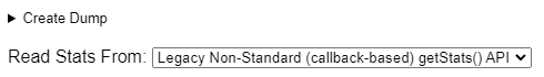
- Run Google Chrome and go to:
chrome://webrtc-internals
- Select read stats from
Legacy Non-Standard.
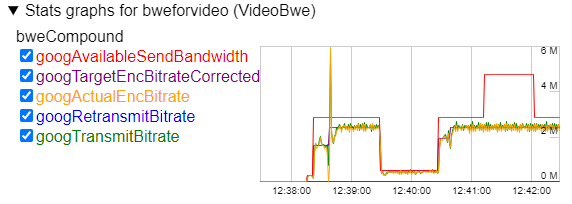
- Look for
Stats graphs for bweforvideo (VideoBwe).